

Date.
A recent paper by Smith et al., “Transition-edge sensor characteristics in a modified bias circuit for multiplexed readout,”has been accepted for publication in the IEEE Transactions on Applied Superconductivity. The work addresses an important aspect of X-IFU detector readout: the impact of incorporating a bypass resistor into the bias circuit used for time-division multiplexing (TDM).
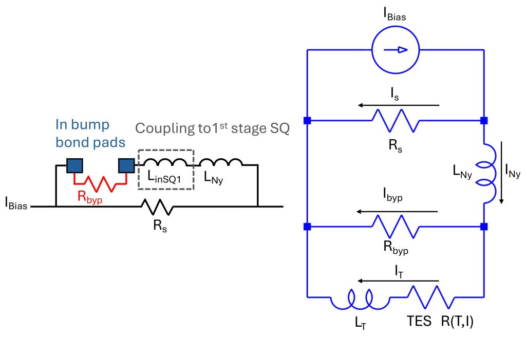
The bypass resistor enables independent screening and characterization of TDM SQUID readout chips fabricated and screened at NIST prior to their integration with the full transition-edge sensor (TES) array — a key requirement for efficient production and qualification of the X-IFU readout system. A lower bypass resistance improves SQUID screening by increasing signal amplitude and signal-to-noise during unit-cell testing, enabling more precise extraction of circuit parameters such as mutual inductance and continuity. Conversely, a higher bypass resistance minimizes the impact on the TES bias circuit once the detectors are connected, introducing a clear trade-off between readout-chip screening capability and detector performance.
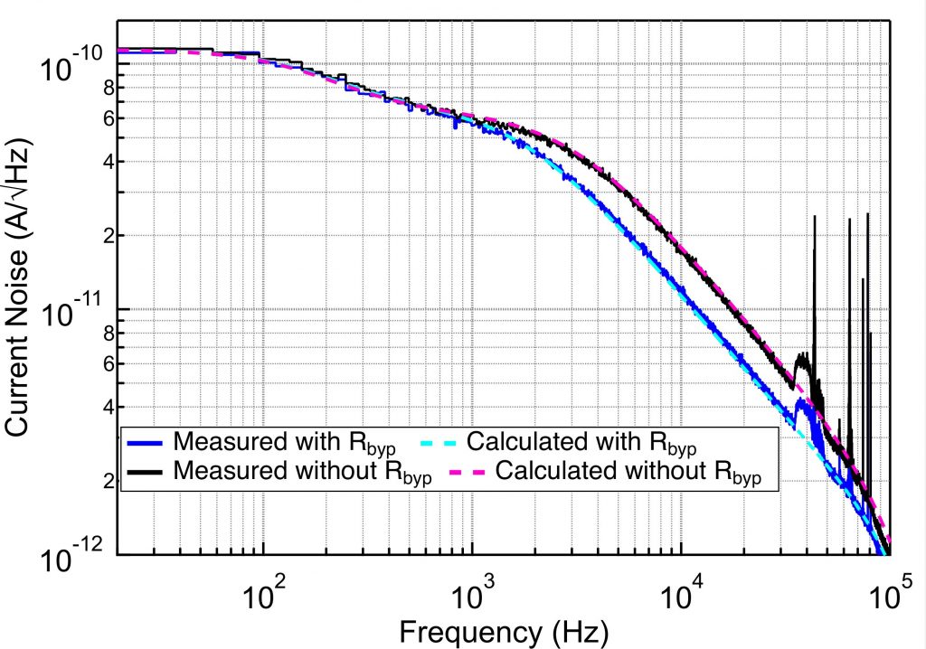
In this study, the authors combine analytical circuit modeling, numerical simulations, and preliminary experimental measurements to quantify how the bypass resistor affects TES noise, bandwidth, pulse dynamics, and energy resolution. The results show that when the bypass resistance is sufficiently larger than the TES dynamic resistance, its impact on detector performance is modest and well understood. The dominant effects are predictable changes in bandwidth and slew rate, with minimal impact on achievable energy resolution for the X-IFU baseline design.
This work represents a collaborative effort across multiple institutions involved in X-IFU instrument development, including NASA Goddard Space Flight Center (GSFC), SRON Netherlands Institute for Space Research, the National Institute of Standards and Technology (NIST), the Erlangen Centre for Astroparticle Physics (ECAP/Bamberg), and the Centre National d’Études Spatiales (CNES). The results provide practical guidance for readout optimization and contribute to the broader understanding of TES behavior in realistic multiplexed bias circuits, supporting the ongoing development of the X-IFU instrument.
Further Resource
- Scientific paper : S. J. Smith et al., “Transition-Edge Sensor Characteristics in a Modified Bias Circuit for Multiplexed Readout,” in IEEE Transactions on Applied Superconductivity, vol. 36, no. 6, pp. 1-7, Sept. 2026, Art no. 2101107, doi: 10.1109/TASC.2026.3664193
![]()
 LinkedIn
 X (ex-Twitter)
 Youtube