
The X-IFU detectors
The X-IFU relies on a cryostat and a cooling chain which enable the prime and the cryogenic anti-coincidence detectors to operate. The prime X-IFU detector is a large array of about 1500 X-ray absorbers on top of highly-sensitive micro-calorimeters called Transition Edge Sensors. The micro-calorimeters sense the heat generated by X-ray photons when they are absorbed and thermalised. The cryogenic anti-coincidence detector is also made of transition edge sensors. A background particle hitting the prime detector will generate a signal similar to the one generated by an X-rays. The same particle will also be detected by the cryogenic anti-coincidence detector. Hence by rejecting simultaneous events occurring in the two detectors, the instrumental background can be reduced.
The interface between the cryostat and the cold part of the X-IFU is provided by an aperture cylinder which holds thermal filters blocking the thermal infrared, visible, ultraviolet, and radio-frequency radiations, while ensuring high transmission of X-rays.
Amplification and Multiplexing
The tiny signal associated with the detection of an X-ray is amplified by closely located cryogenic electronics. The prime detector is made of several thousand transition edge sensors. To operate and read them out, while minimising the heat loads on the cryogenic chain, the sensors are grouped and read out in about a hundred channels, using a multiplexing technique.
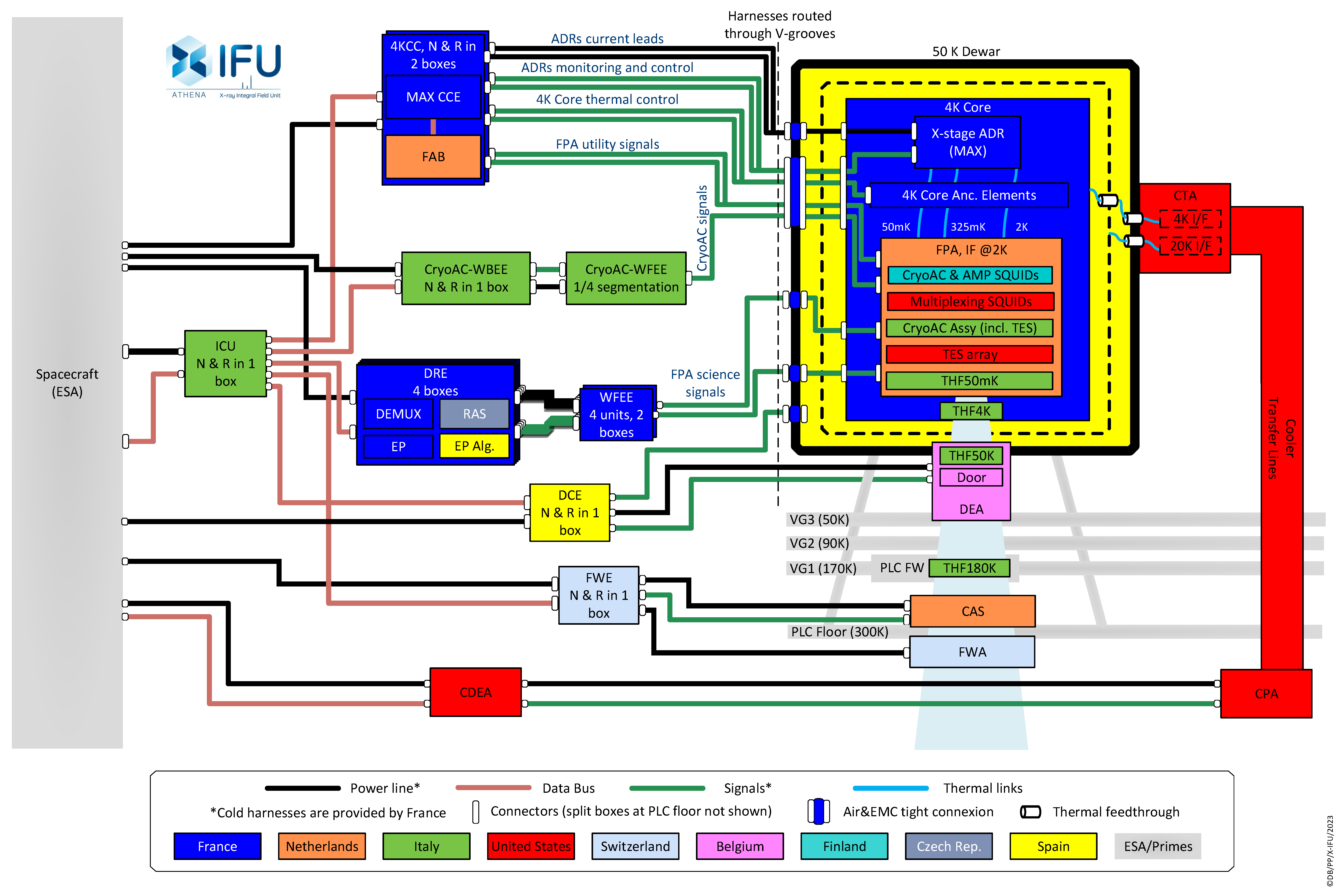
The amplified signal is then extracted from the cryostat through cold harnesses, which carry the signal to readout electronics at warm temperatures. The readout electronics further amplify the signal, which is then processed to give information about the detected X-ray (energy, position, arrival-time). A similar electronic chain takes care of the cryogenic anti-coincidence detector.
Auxiliary equipment
The X-IFU also consists of power and control electronics which powers the instrument sub-systems, regulates the temperature of the focal plane assembly, and provides monitoring data of the different subsystems. To perform an observation, the instrument must be calibrated regularly, and this is achieved through an on-board calibration source.
Finally, to enable the observer to choose its optimised observation set-up, various filters can be selected, for instance to block undesired optical photons emitted by the observed target. Those filters are held by the filter wheel.
Cryogenic architecture
The X-IFU cryogenic architecture relies on a passive cooling system implemented by the Payload Compartment, based on a set of three L-shape cryogenic radiators, called V-grooves, providing a 50K environment to the Instrument and a cryogenic system implemented by X-IFU, providing the cooling capacity to the detector stage, starting from the 50K environment. It includes: a Dewar vessel with an outer envelope at 50K, which hosts the Instrument Cold Core containing the detector, a remote cryocooler, called 4K Cooler, providing active cooling to the Instrument inner stages in the 20K and 4K ranges and a multi-stage Adiabatic Demagnetization Refrigerator (ADR), able to cool the detector stage down to 50mK starting from the 4K stage.
 LinkedIn
 X (ex-Twitter)
 Youtube